


Hot Products
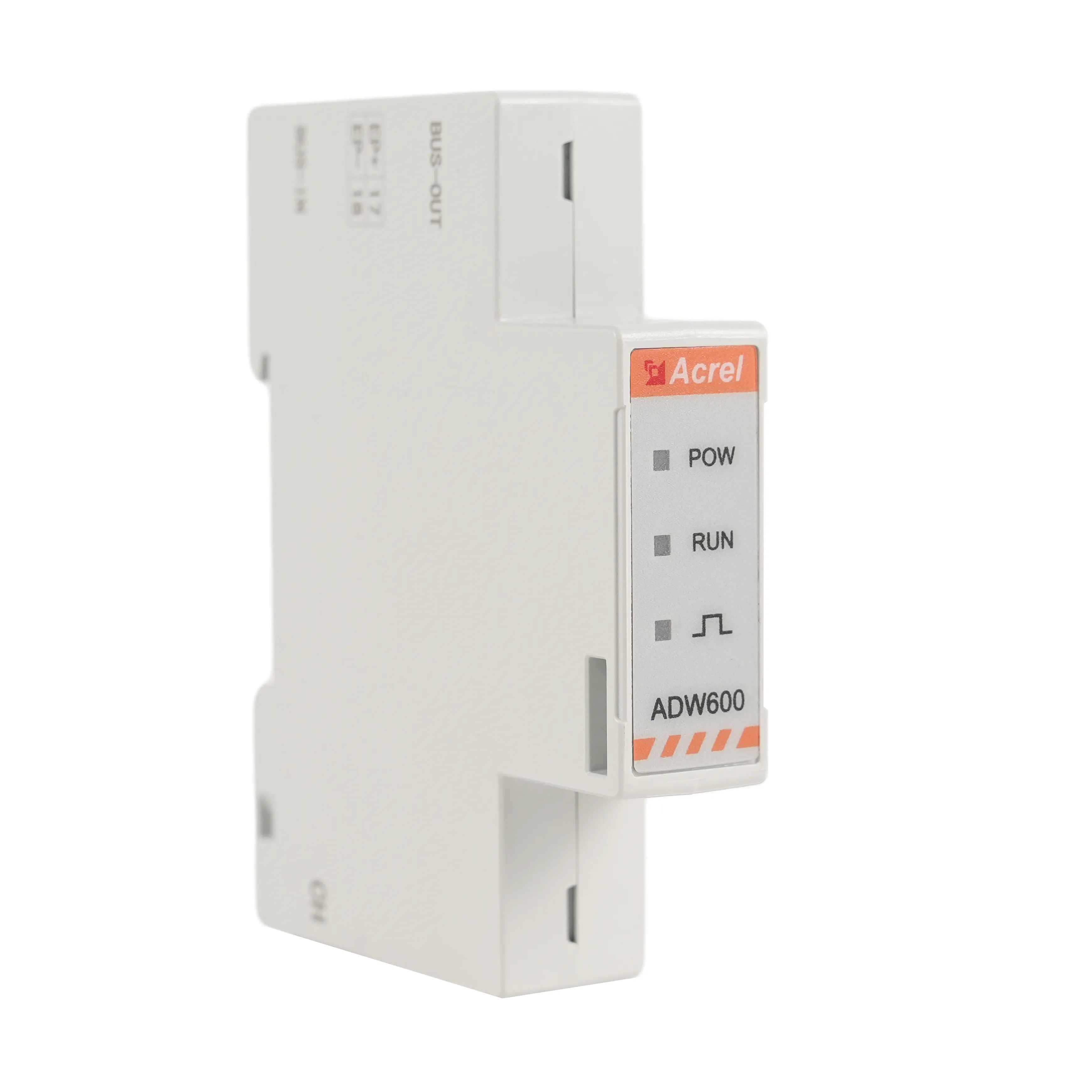
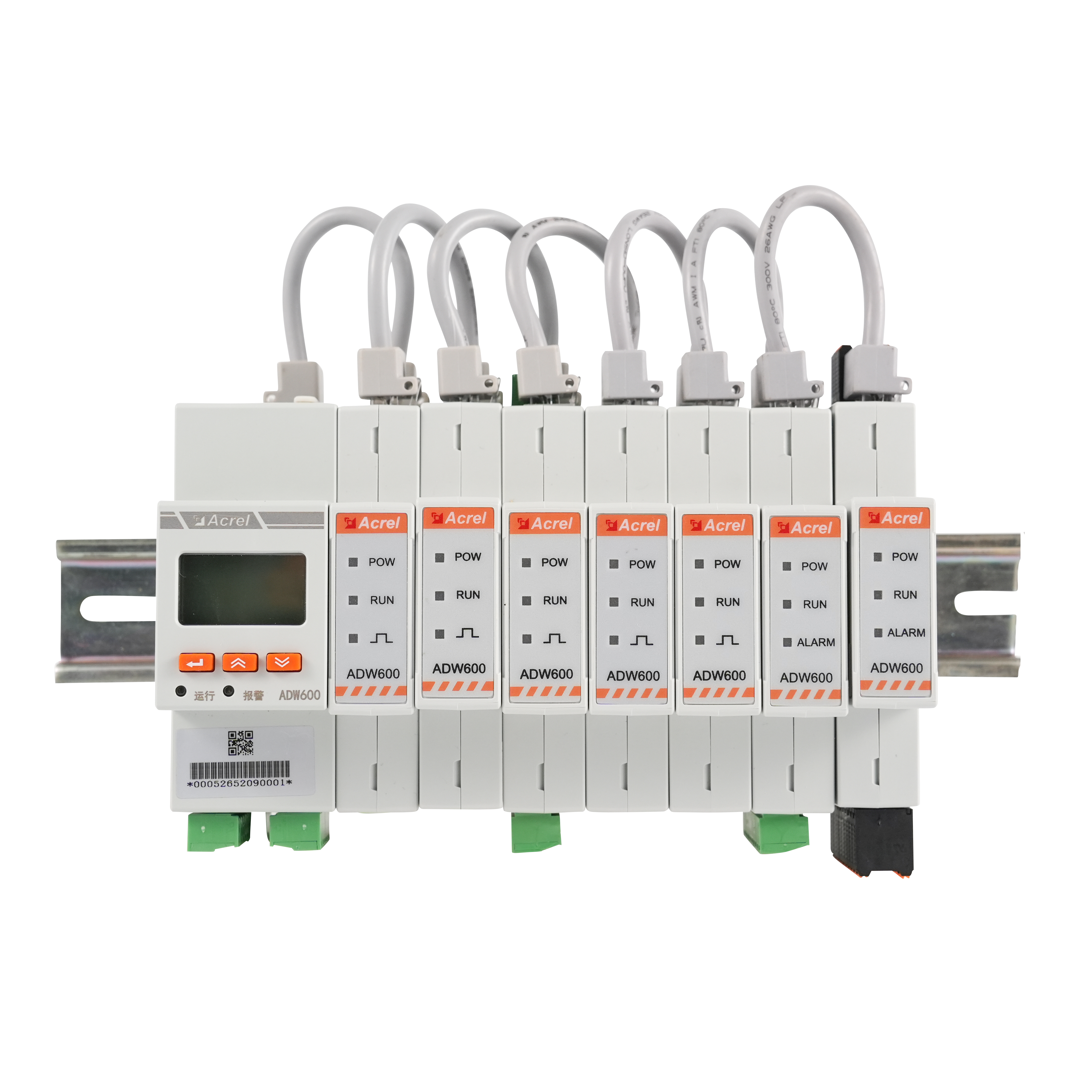
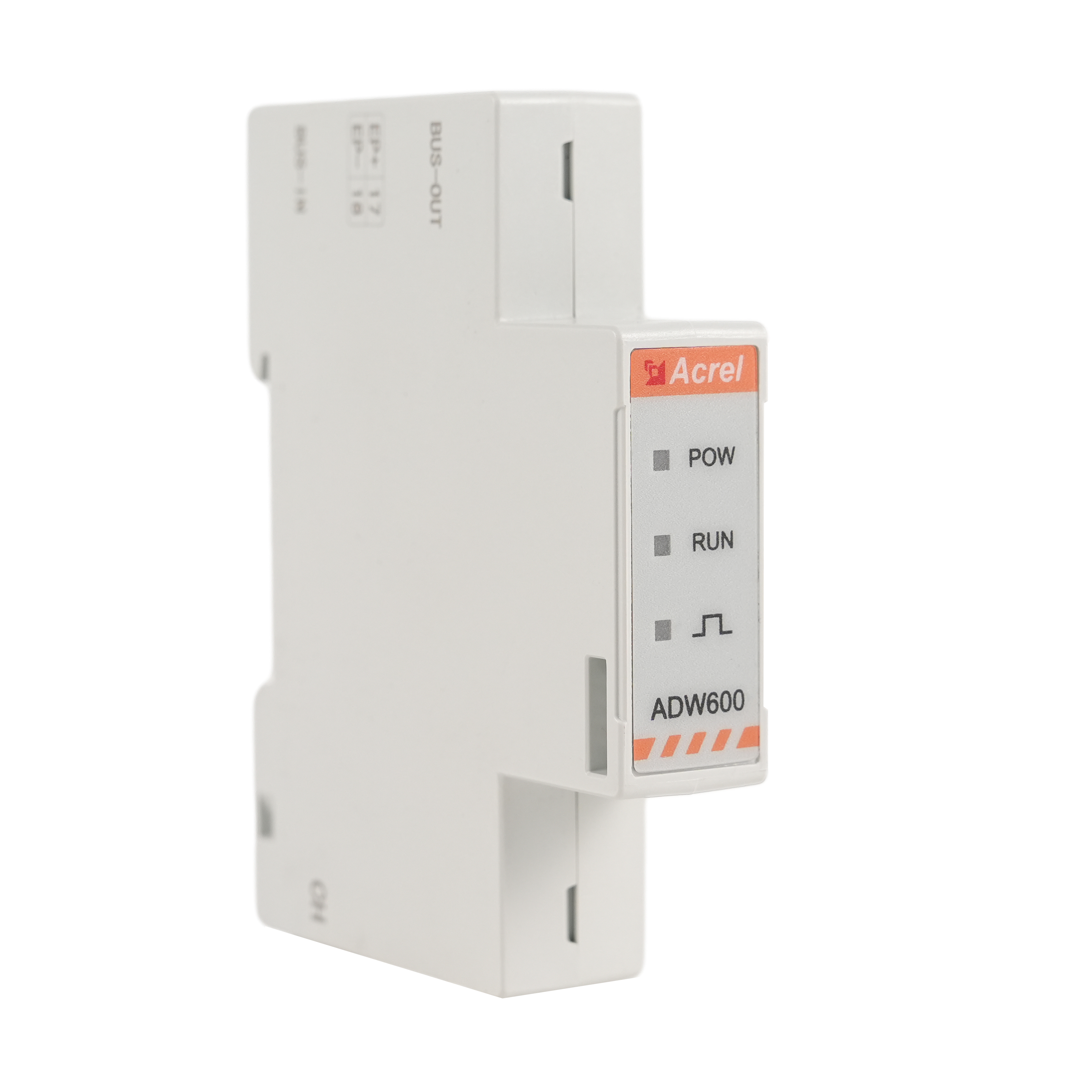
Acrel ADW600 Multi Channels Smart 3 Phase Energy Meter
With Different Size of CTs,easy to install D10,D16,D24,D36
The ADW600 multi circuit power metering module is mainly used to measure three-phase active energy in low-voltage networks, and has the advantages of small size, easy installation, and rich functions. The product adopts a modular design, including voltage module, current module, switch module, temperature measurement and leakage module, etc. The modules are connected by Ethernet cables and can support multi circuit splicing. Suitable for low-voltage side multi circuit metering scenarios, especially for power transformation needs.
 |
Main Feature
● Full electric parameter measurement,Multi Channels independent metering
● With Different Size of CTs,easy to install D10,D16,D24,D36
● RS485 standard, Optional 4G Ethernet or WIFI
● Optional 4DI2DO,12 channels temp measure,4 channels Residual current monitoring
● Application: for the Multi channels places
Parameter
|
ADW600-U |
Rated voltage |
3×57.7/100V, 3×220/380V, 3×100V, 3×380V |
|
Voltage accuracy |
0.5% |
|
|
Reference frequency |
45-65 Hz |
|
|
Power consumption |
<0.5VA per phase |
|
|
ADW600-I |
Input Current |
D10:0.03-0.15(6)A, D16:0.8-2(100)A, D24:3.2-8(400)A, D36: 4.8-12(600)A |
|
Active energy accuracy |
Class B |
|
|
Energy pulse width |
80±20ms |
|
|
Active pulse constant |
D10: 6400 imp/kWh , D16: 400 imp/kWh , D24: 100 imp/kWh , D36: 60 imp/kWh |
|
|
Power consumption |
<1VA per phase |
|
|
ADW600-K |
Switch input |
4-way passive input, built-in DC12V power supply |
|
Switching output |
2-way passive output, capacity AC230V/DC30V, 3A |
|
|
ADW600-TL |
Temperature measurement |
12-channel temperature measurement, accuracy ±2°C, 12 temperature measurement lines as standard |
|
Residual current measurement |
4-way residual current measurement, input maximum 1mA, accuracy 1%, residual current transformer needs to be purchased separately |
|
Temperature range |
Operating temperature |
-25 ℃ ~ 55 ℃ |
|
Storage temperature |
-40 ℃ ~ 70 ℃ |
|
|
humidity |
≤95% (no condensation) |
|
|
altitude |
<2000m |
|
Dimension

1. The ADW600-M gateway (-4G/-CE/-WF) on the far left of the ADW600 rendering in Figure 1 needs to be ordered separately.
2. When connecting network cables between different modules, please note that BUS-IN is the incoming interface and BUS-OUT is the outgoing interface. Start with ADW600-M or the power module and connect them in sequence. Do not connect them in reverse.
|
Specifications: Model |
Overall dimensions (mm) |
Perforation size (mm) |
Tolerance (mm) |
|||||
|
W |
H |
D |
M |
N |
Φ1 |
Φ2 |
||
|
D10:AKH-0.66/K- ∅10N |
27 |
44 |
32 |
25 |
36 |
10 |
9 |
±1 |
|
D16:AKH-0.66/K-∅16N |
31 |
50 |
36 |
27 |
42 |
16 |
17 |
|
|
D24:AKH-0.66/K-∅24N |
39 |
71 |
46 |
36 |
52 |
24 |
23.5 |
|
|
D36:AKH-0.66/K-∅36N |
42.5 |
82 |
58 |
40 |
56 |
33.5 |
35 |
|

Wiring
ADW600 multi-circuit metering modules are connected by network cables. BUS-IN is the incoming interface and BUS-OUT is the outgoing interface. They are connected starting from ADW600-M or the power module and cannot be connected in reverse.
ADW600 -U needs to be connected to the load voltage signal. Refer to the wiring diagram below. Terminals 11-14 are connected to the UA, UB, UC, and UN voltage signals respectively. If the three-phase three-wire connection method is used, terminals 11-13 are connected to the UA, UB, and UC voltage signals, and then UB is short-circuited into the UN terminal.

ADW600 -I needs to be connected to the load current signal. Refer to the wiring diagram below. The standard transformer is an RJ12 interface that can be inserted into the meter terminal. The three transformers can be clipped onto the load cables according to the indicated directions.

ADW600 -K is connected to the switch input or output signal line as needed. Note that the COM port is the common end. Refer to the wiring diagram below.

ADW600 -TL is connected to the temperature measurement signal line or the residual current transformer signal line as needed. Note that the COM port is the common end of the adjacent measurement circuits. The specific wiring diagram is as follows.

Acrel ADW600 Multi Channels Smart 3 Phase Energy Meter
Optional 4DI2DO,12 channels temp measure,4 channels Residual current monitoring
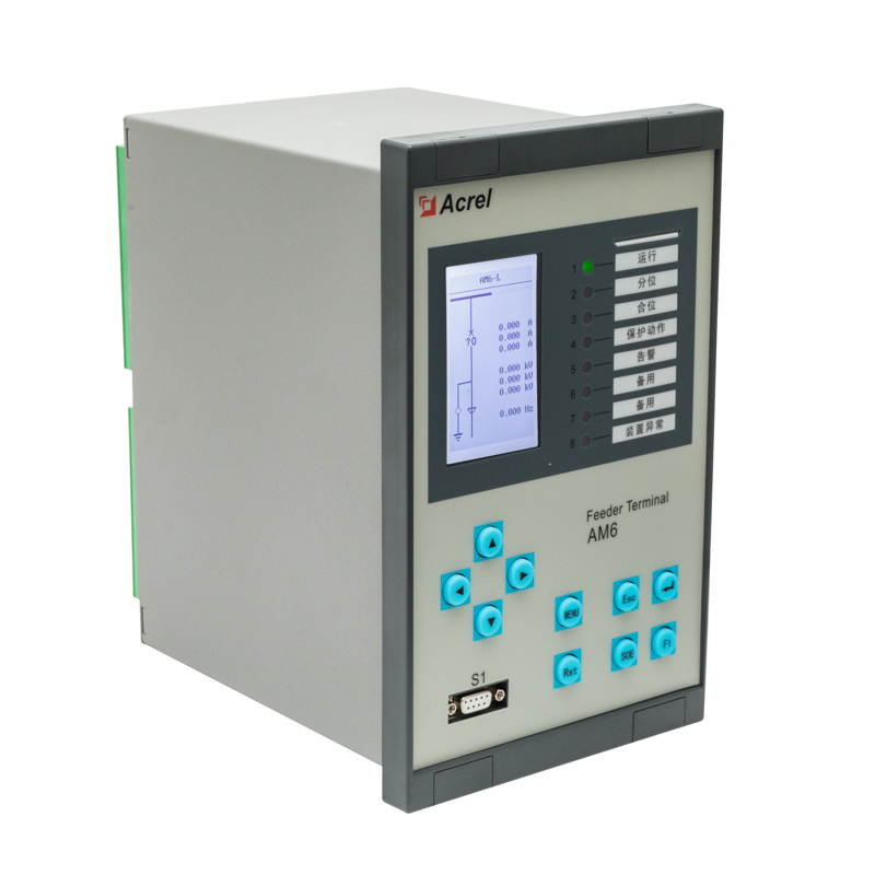
AM6 Prefabricated Substation Protection & Control Device
2 × 4–20 mA DC measurement channels and 3 temperature measurement channels
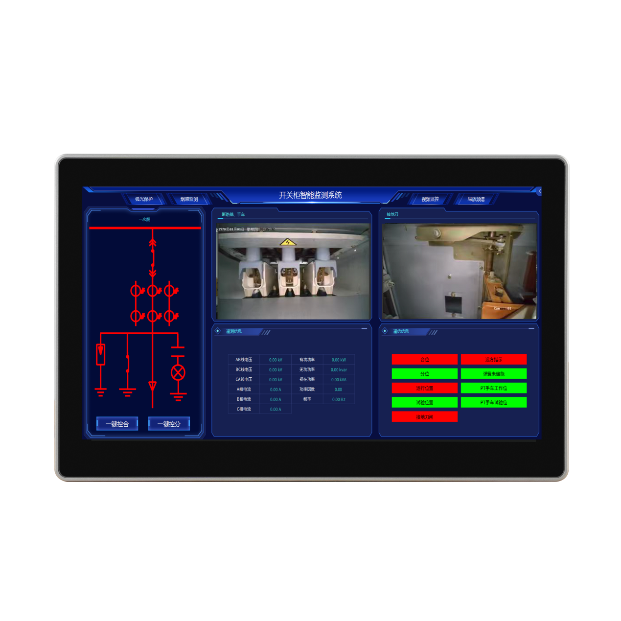
ATU Intelligent Monitoring Terminal for Switchgear
Conduct centralized monitoring and management.
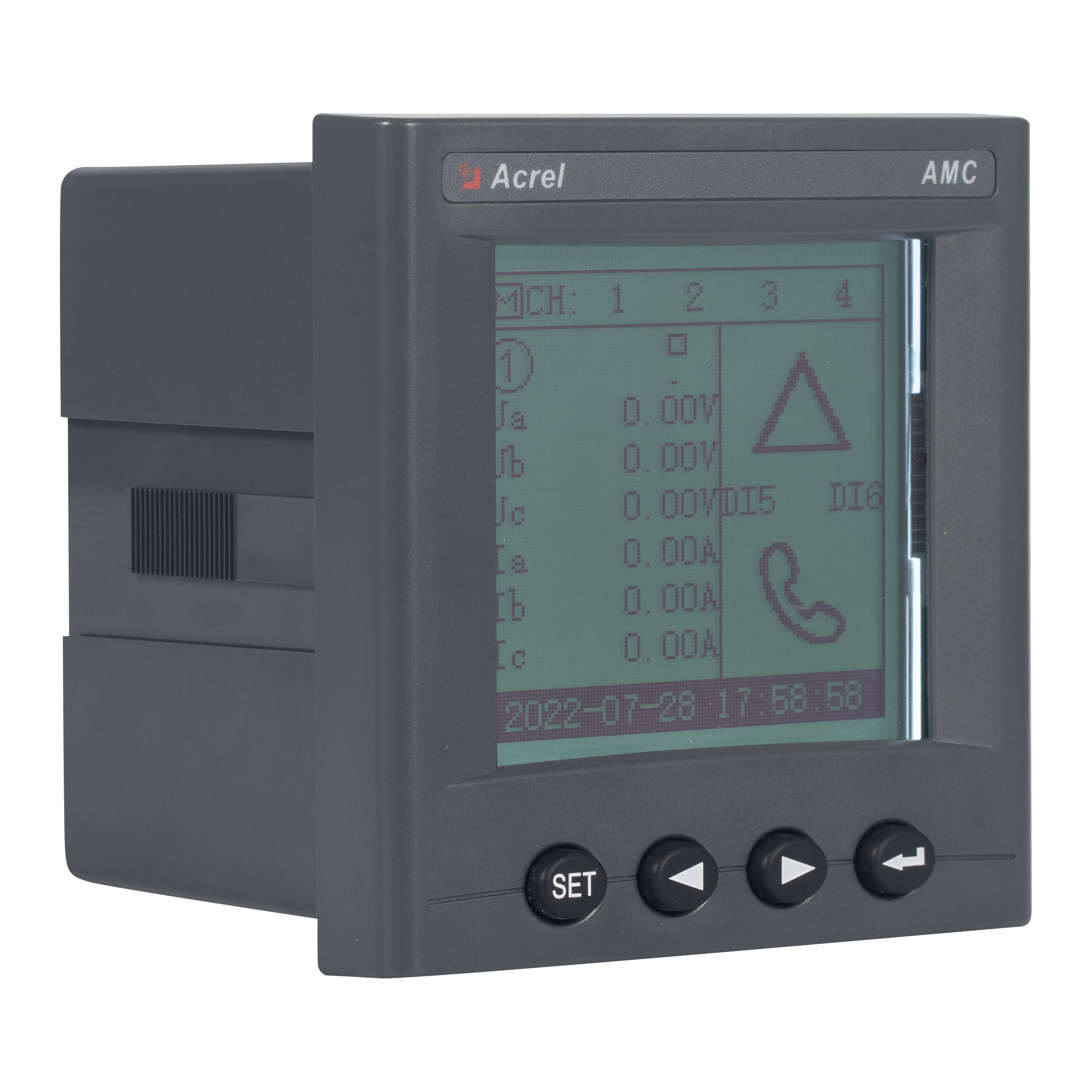
AMC300L Base Station AC Multi-loop Intelligent Power Collection and Monitoring Device
6 channel 3 phase or 18 channel 1 phase
Acrel ADW600 Multi Channels Smart 3 Phase Energy Meter
With Different Size of CTs,easy to install D10,D16,D24,D36
Acrel ADW600 Multi Channels Smart 3 Phase Energy Meter
Optional 4DI2DO,12 channels temp measure,4 channels Residual current monitoring
AM6 Prefabricated Substation Protection & Control Device
2 × 4–20 mA DC measurement channels and 3 temperature measurement channels
ATU Intelligent Monitoring Terminal for Switchgear
Conduct centralized monitoring and management.
AMC300L Base Station AC Multi-loop Intelligent Power Collection and Monitoring Device
6 channel 3 phase or 18 channel 1 phase
Acrel ADW600 Multi Channels Smart 3 Phase Energy Meter
With Different Size of CTs,easy to install D10,D16,D24,D36
Acrel ADW600 Multi Channels Smart 3 Phase Energy Meter
Optional 4DI2DO,12 channels temp measure,4 channels Residual current monitoring
AM6 Prefabricated Substation Protection & Control Device
2 × 4–20 mA DC measurement channels and 3 temperature measurement channels
ATU Intelligent Monitoring Terminal for Switchgear
Conduct centralized monitoring and management.
Inquiry
If you have any suggestions or question for us.Please contact us